Network Map
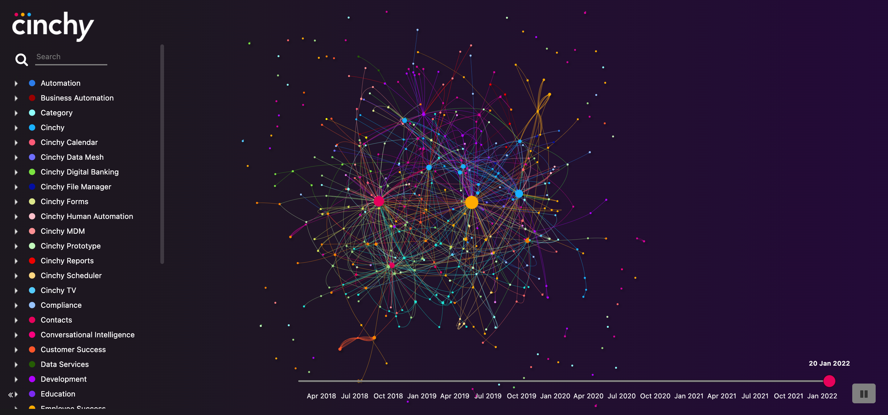
Cinchy comes out of the box with a system applet called Network Map (Image 1), which is a visualization of your data on the platform and how everything interconnects.
My Data Network is another way to view and navigate the data you have access to within Cinchy.
Each node represents a table you have access to within Cinchy, and each edge is one link between two tables. The size of the table is determined by the number of links referencing that table. The timeline on the bottom allows you to check out your data network at a point in the past and look at the evolution of your network.
It uses the user's entitlements for viewable tables and linked columns.
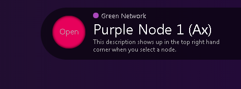
When you click on a node, you will see its description in the top right hand corner. You can click the Open button to navigate to the table (Image 2).
You will find the Network Map data experience on the Homepage (Image 3).
Custom network visualizer
You can also set up a custom network visualizer as follows:
Nodes
The nodes query defines the nodes in the network (Image 4 and 5).
| Parameter | Description |
|---|---|
| id | Id for the node. This will be used by the edges to define the relationships. |
| title | This is the text that's displayed when hovering on a node. |
| label | The label shown below the node. |
| value | The visual size of the node relative to other nodes. |
| mass | The gravitational pull of a node. Unless you really want to customize the visualizer, it's recommended to keep this the same value as the value. |
| group | Optionally you can associate a node with a group. |
| color | Optional hex code for the color of a node. The node will take the color of the group if a color isn't specified for the node. |
| description | The description shows up in the top right hand corner when you click a node. |
| nodeURL | Page to display when you click the open button next to the description. |

Edges
The edges query defines the relationships between the nodes (Image 6).
| Parameter | Description |
|---|---|
| id | Id for the edge. |
| label | Label that shows up on the edge. |
| from | Originating node id. |
| to | Target node id. Can be the same as the from node, it will show a loop back into the same node. |
| showArrowTo | Set this to True if you want to show the direction of the relationship. |
| showArrowFrom | Generally should only be used for bi-directional relationships along with the arrow to. |
Node groups
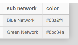
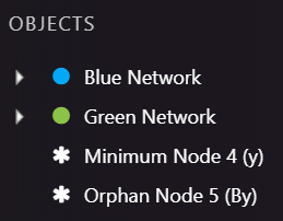
Node groups are an optional query you can provide to group your nodes (Image 7 and 8).
| Parameter | Description |
|---|---|
| sub network | Name for the group |
| color | Hex value for the color of the group |
Timeline
If no start or end date is specified, the data network is just shown as is. If there's a start or end date, the other CQL queries must have a @date parameter and that will be used to render the data network at a point in time.
You can use @date between [Modified] and [Replaced] with a version history query to see data at a specific time. You can also simply use @date > [Created] if it's an additive system.
Timeline start date
This CQL should return a date value as startDate.
Timeline end date
This CQL should return a date value as endDate.
Slicers
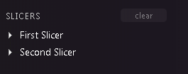
To use slicers, you must define the slicers in the Slicers column and add the additional attributes to the nodes query.
[
    {
        "attribute": "slice1",
        "displayName": "First Slicer"
    },
    {
        "attribute": "slice2",
        "displayName": "Second Slicer"
    }
]
Attribute is the column name from the nodes query, displayName is what shows up in the visualizer (Image 9 and 10).
System tables
All the information above is entered into the [Cinchy].[Networks] table. To access the network, go to:
<Cinchy URL>/Cinchy/apps/datanetworkvisualizer?network=<NAME>
Alternatively you can go to My Data Network and then add ?network=<NAME> to the end of it.
It's highly recommended to add a new applet for each custom data network visualizer for ease of access.
Optional URL parameters
Cinchy version 5.2 added the ability to include new parameters on the URL path for your network visualizer to focus your node view. You can now add Target Node, Depth Level, and Max Depth Level Parameters, if you choose.
Example: <base url>/apps/datanetworkvisualizer?targetNode=\&maxDepth=\&depthLevel=
- Target Node: Using the Target Node parameter defines which of your nodes will be the central node from which all connections branch from.
- Target Node uses the TableID number, which you can find in the URL of any table.
- Example:
<base url>/apps/datanetworkvisualizer?targetNode=8will show TableID 8 as the central node
- Max Depths: This parameter defines how many levels of network hierarchy you want to display.
- Example:
<base url>/apps/datanetworkvisualizer?maxDepth=2will only show you two levels of connections.
- Example:
- Depth Level: Depth Level is a UI parameter that will highlight/focus on a certain depth of connections.
- Example:
<base url>/apps/datanetworkvisualizer?DepthLevel=1will highlight all first level network connections, while the rest will appear muted.
- Example:
The below example visualizer uses the following URL: <base url>/apps/datanetworkvisualizer?targetNode=8\&maxDepth=2\&depthLevel=1
- It shows Table ID 8 ("Groups") as the central node.
- It only displays the Max Depth of 2 connections from the central node.
- It highlights the nodes that have a Depth Level of 1 from the central node.
Example network
The following is an example of a network map (Image 11).
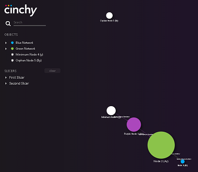
For ease of testing, save the following as saved queries and then in the Networks table, add exec [Domain].[Saved Query Name] as the CQL queries.
Node groups CQL
-- Sample Data
SELECT
  [Sub Network] = 'Blue Network'
, [Color] = '#03a9f4'
INTO #TEMP
UNION SELECT
  [Sub Network] = 'Green Network'
, [Color] = '#8bc34a'
-- Node Groups CQL
SELECT
  t.[Sub Network] as 'sub network'
, t.[Color] as 'color'
FROM #TEMP t
Nodes CQL
-- Sample Data
SELECT
   [Id] = 'N01'
,  [Title] = 'Hover text on the node.'
,  [Label] = 'Purple Node 1 (Ax)'
,  [Value] = 5
,  [Mass] = 5
-- optional
,  [Group] = 'Green Network'
,  [Color] = '#ab47bc'
,  [Description] = 'This description shows up in the top right hand corner when you select a node.'
,  [Node URL] = 'https://www.cinchy.com'
,  [Slicer 1] = 'A'
,  [Slicer 2] = 'x'
INTO #TEMP
UNION SELECT
   [Id] = 'N02'
,  [Title] = 'Hover text on node 2.'
,  [Label] = 'Node 2 (Ay)'
,  [Value] = 10
,  [Mass] = 10
-- optional
,  [Group] = 'Green Network'
,  [Color] = ''
,  [Description] = 'This description shows up in the top right hand corner when you select a node.'
,  [Node URL] = ''
,  [Slicer 1] = 'A'
,  [Slicer 2] = 'y'
UNION SELECT
   [Id] = 'N03'
,  [Title] = 'Hover text on node 3.'
,  [Label] = 'Node 3 (Bx)'
,  [Value] = 1
,  [Mass] = 1
-- optional
,  [Group] = 'Blue Network'
,  [Color] = ''
,  [Description] = ''
,  [Node URL] = ''
,  [Slicer 1] = 'B'
,  [Slicer 2] = 'x'
UNION SELECT
   [Id] = 'N04'
,  [Title] = 'Hover text on node 4.'
,  [Label] = 'Minimum Node 4 (y)'
,  [Value] = 3
,  [Mass] = 3
-- optional
,  [Group] = ''
,  [Color] = ''
,  [Description] = ''
,  [Node URL] = ''
,  [Slicer 1] = ''
,  [Slicer 2] = 'y'
UNION SELECT
   [Id] = 'N05'
,  [Title] = 'Hover text on node 4.'
,  [Label] = 'Orphan Node 5 (By)'
,  [Value] = 2
,  [Mass] = 2
-- optional
,  [Group] = ''
,  [Color] = ''
,  [Description] = ''
,  [Node URL] = ''
,  [Slicer 1] = 'B'
,  [Slicer 2] = 'y'
-- Nodes CQL
SELECT
   t.[Id] as 'id'
,  t.[Title] as 'title'
,  t.[Label] as 'label'
,  t.[Value] as 'value'
,  t.[Mass] as 'mass'
,  t.[Group] as 'group'
,  t.[Color] as 'color'
,  t.[Description] as 'description'
,  t.[Node URL] as 'nodeURL'
,  t.[Slicer 1] as 'slice1'
,  t.[Slicer 2] as 'slice2'
FROM #TEMP t
Edges CQL
-- Sample Data
SELECT
  [Id] = 'E01'
, [Label] = 'Node 1 to Node 2, Double Arrows'
, [From] = 'N01'
, [To] = 'N02'
-- optional
, [Show Arrow To] = 'True'
, [Show Arrow From] = 'True'
INTO #TEMP
UNION SELECT
  [Id] = 'E02'
, [Label] = 'Node 2 to Node 3, To Arrow'
, [From] = 'N02'
, [To] = 'N03'
-- optional
, [Show Arrow To] = 'True'
, [Show Arrow From] = 'False'
UNION SELECT
  [Id] = 'E03'
, [Label] = 'Node 1 to Node 4, From Arrow'
, [From] = 'N01'
, [To] = 'N04'
-- optional
, [Show Arrow To] = ''
, [Show Arrow From] = 'True'
UNION SELECT
  [Id] = 'E04'
, [Label] = 'Node 3 to Node 3, No Arrow'
, [From] = 'N03'
, [To] = 'N03'
-- optional
, [Show Arrow To] = ''
, [Show Arrow From] = ''

-- Edges CQL
SELECT
   t.[Id] as 'id'
,  t.[Label] as 'label'
,  t.[From] as 'from'
,  t.[To] as 'to'
,  t.[Show Arrow To] as 'showArrowTo'
,  t.[Show Arrow From] as 'showArrowFrom'
FROM #TEMP t